This project will show you how to build your own rolling dolly for telescope.
Most medium-sized mounts and telescopes are too heavy and unwieldy to move once they’ve been assembled, which means setting up and packing away each night can become a slog.
There are the numerous journeys back and forth to the garden, for one.
Refitting mount heads and weights takes up time when you could be out observing, and rebalancing a telescope can be fiddly work in the dark.

It is also all too easy to misplace leads and small parts.
A rolling telescope dolly could help ease your setup process and help you get on with observing the night sky.
Leave your fully assembled setup on top of it and whenever the skies are clear you can simply roll the whole unit into position.
If the weather turns against you, you can be back in the warm in next to no time, secure in the knowledge that nothing is left behind.
Download extra plans to help with the build
- Build a telescope dolly – overview (PDF)
- Build a telescope dolly – beams (PDF)
- Build a telescope dolly – plates (PDF)

Telescope dolly tools and materials
Tools
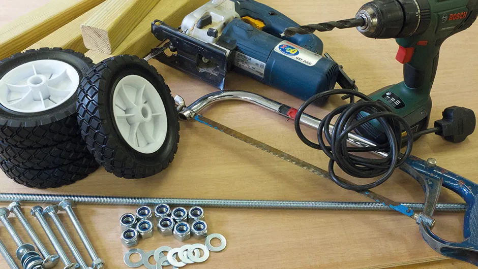
Handsaw or jigsaw, hacksaw, drill and bits (for 12mm and 8mm bolts), spanners, screwdriver.
Materials
Approximately 3m of 45x45mm construction timber, 1,200x600mm sheet of 9mm plywood, length of suitable timber or rope for the handle
Sundries
Four 150mm-diameter wheels with rubber tyres, 1m of M12 studding (diameter to suit wheels) with nuts and washers, six M8x75 bolts, 75mm butt hinge, epoxy resin glue, 25mm woodscrews.
Finish
Preservative wood stain or paint
Getting started
The timber for the dolly’s axles can be readily obtained from a builder’s merchant.
We chose ‘prepared’ (planed) 45x45mm timber because it is nice to handle and can be painted to match your other equipment.
The plywood parts provide bracing: we made ours from 9mm thick sheet, but you could use a slightly different thickness if you already have some available.
The dolly frame needs to be rigid, but as most of the scope’s weight is supported close to the wheels it doesn’t need to be too heavy.
Individual parts are bolted together, allowing you to take the dolly apart for easy storage or transport.
Furthermore, the design allows for re-sizing should you ever decide to upgrade your tripod.
You can download plans to help with the build at the top of this article.
They show dimensions for our example dolly, and these measurements should suit most small to medium tripods.
We have indicated the positions we drilled holes in the bracing plates, but we’d recommend lining up your beams and tripod support plates with your own tripod to determine the best position for these holes before drilling.
Ideally the wheels and jacking points should be as close to the tripod feet as possible.
For wheels, we chose 150mm plastic ones with rubber tyres.
These run well on M12 studding axles and they seem to cope with regular gravel drives and garden lawns.
Because the speeds involved are low and distances relatively short, pneumatic tyres and proper bearings are not necessary.
Unless you are scaling up the design for a heavyweight mount or you have particularly bumpy ground to cover.

Finessing the design
If your tripod legs have slightly pointed feet, a simple hole drilled in the leg support plate will help locate them.
If you have a tubular design you could make L-shaped corner blocks and screw them into each plate to prevent your tripod from sliding off.
Tying your tripod down with straps or bungees is also a good idea, in case you bump against something or have to stop suddenly.
The last thing you want is for your setup to pitch forward and crash to the ground.
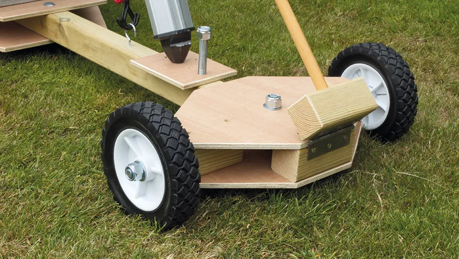
On the front of the dolly is a rigid towing handle.
It attaches to the front of the steering mechanism via a hinge, so it can be folded back against the tripod when not in use.
You could also use a loop of rope or webbing as a simpler alternative.
When you have your dolly in position, screw down the jacks to stop it moving accidentally.
Once you are polar aligned, you could also mark the jack positions on the ground to aid repositioning on future nights.
We also found that the bracing plate below the tripod is ideal for holding accessory cases and a power tank.
But you could consider customising this area to provide specially made racks and boxes for your accessories and imaging equipment.
Building the telescope dolly, step-by-step
Step 1

After carefully marking out the parts, use a saw to cut them to size.
You can tape multiple plywood parts together and cut in one go so they match each other.
If you have access to a band saw or jigsaw you could save some time here.
Step 2

Drill the holes in plywood parts first, then line them up with the axles.
Place your tripod on top to check size. Mark through the holes to find out where to drill into the axles.
Do this, then assemble the timber and plywood parts.
Step 3

Make the steering ‘box’.
It’s held together with 25mm woodscrews inserted through the plywood plates into the axle and front blocks.
A piece of studding provides a pivot.
Use Nylock nuts and washers and make sure it turns smoothly but is not wobbly.
Step 4

Cut lengths of studding for the axles using a hacksaw.
Allow enough for a nut and washer either side of the wheel, plus about 50mm to be glued inside the wood.
File the ends of the studding so they aren’t sharp and the nuts fit on nicely.
Step 5

Check the wheels spin without wobbling.
Use epoxy resin to glue each axle in, taking care not to get any glue on the moving parts.
If the wheel needs to be removed later on you should be able to simply undo the outer nut.
Step 6

Once the tripod foot plates and jack blocks are screwed into position, drill through both for the studding.
An enlarged hole on the underside gives you room to glue in a captive nut (normal type).
Use a Nylock nut (or a wooden disc) to make the upper turning knob.
If you do build our telescope dolly, we'd love to see it! Get in touch by emailing contactus@skyatnightmagazine.com
