Once installed, the process of recording flats is much quicker. Image Credit: Steve Richards
Download a zip folder of templates and a video to help with this project here.
Capturing flat field calibration frames is an essential part of astrophotography if you want to end up with the best possible images.
If you have your imaging setup installed in a permanent observatory, however, there’s a way to cut down on this chore – simply automate the process.
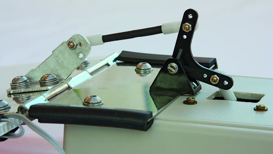
This is achieved by means of this ‘flat flap’, an accessory that moves an electroluminescent panel onto the front of your telescope to produce an even light source.
Not only that, the flap acts as a dust cap until it is automatically opened for the next imaging session.
The design shown here is suitable for telescopes with apertures up to 120mm.
There are six main sections to the construction starting with the flap itself.
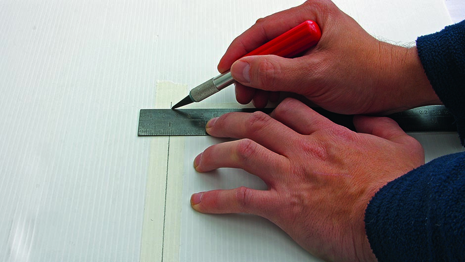
Use a craft knife and a steel ruler to cut your corrugated plastic sheet to a 150x235mm rectangle, with the ‘grain’ running along the long side.
Cut a 25mm wide, 130mm long strip of 1mm plywood and use impact adhesive to fix it to the short edge of the board at the base, leaving a 20mm gap on the right for the electroluminescent panel’s connection point.
Fix the panel to the flap using double-sided tape.
Print the templates (from the link at the top of this article) for the box lid onto a sheet of paper and then the front panel section onto a self-adhesive label.
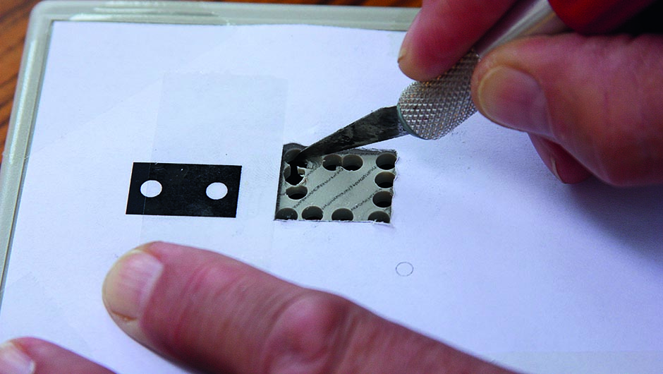
Cut the box lid section to size and cut out the printed rectangular hole. Fix the template to the top section of the box with tape and mark the rectangle on the box.
Chain drill inside the rectangle, then cut between the holes with a craft knife.
Finish by drilling the two 4mm holes for the bellcrank and the two 2mm holes for the servo bracket.
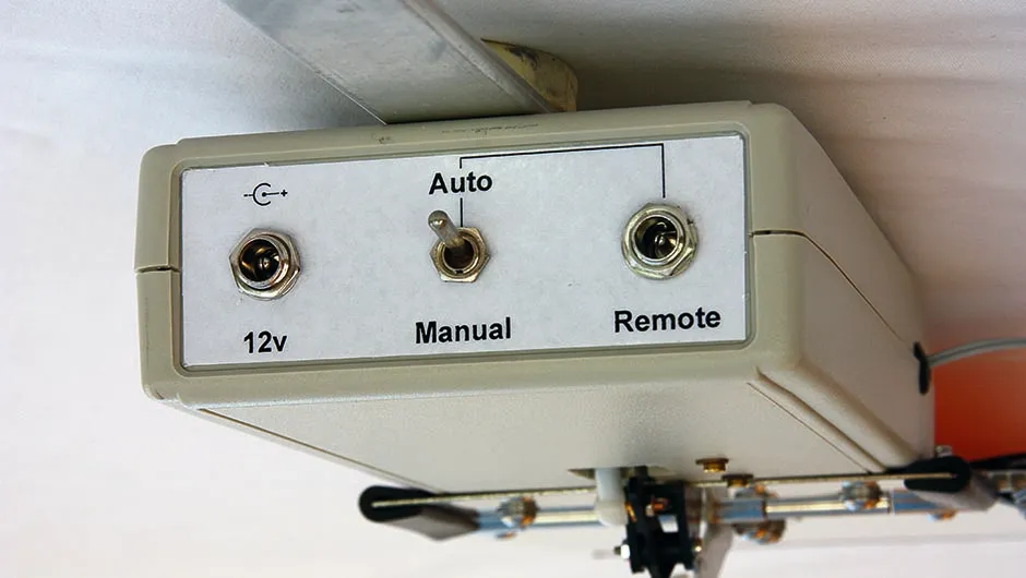
Cover the front panel template with transparent sticky back plastic, cut it to size and attach it to the front panel.
Drill two 8mm holes for the two sockets and a 5.2mm hole for the switch.
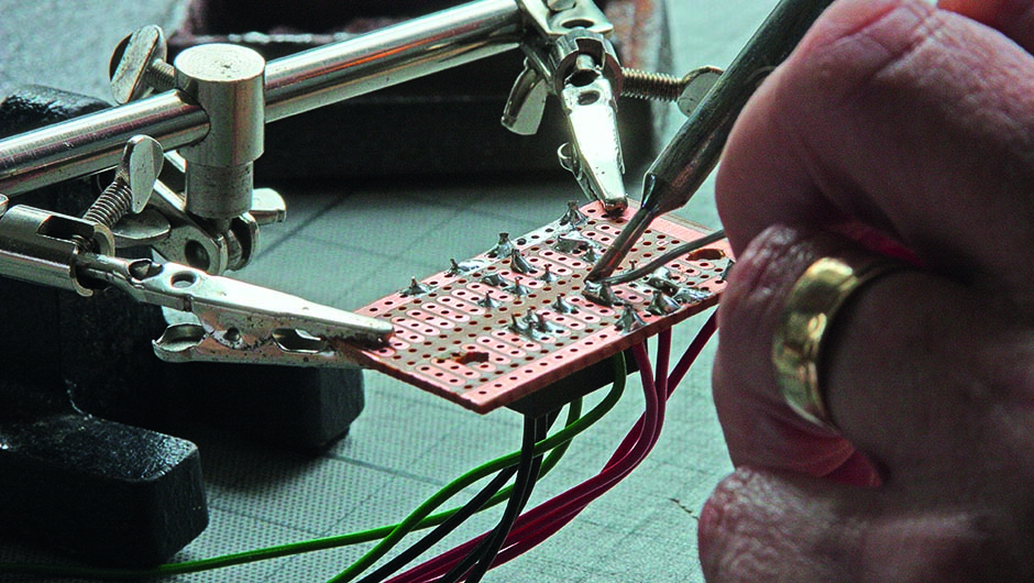
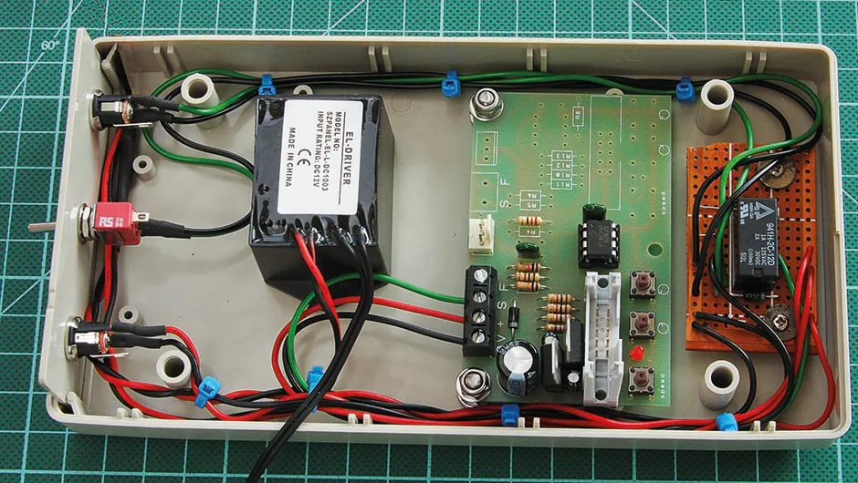
Referencing the circuit and relay pin diagrams available at the link above, carefully solder the circuit together using black wire for negative (–ve) connections, red wire for positive (+ve) connections and green wire for ‘signal’ connections.
Attach the sockets and switch to the front panel.
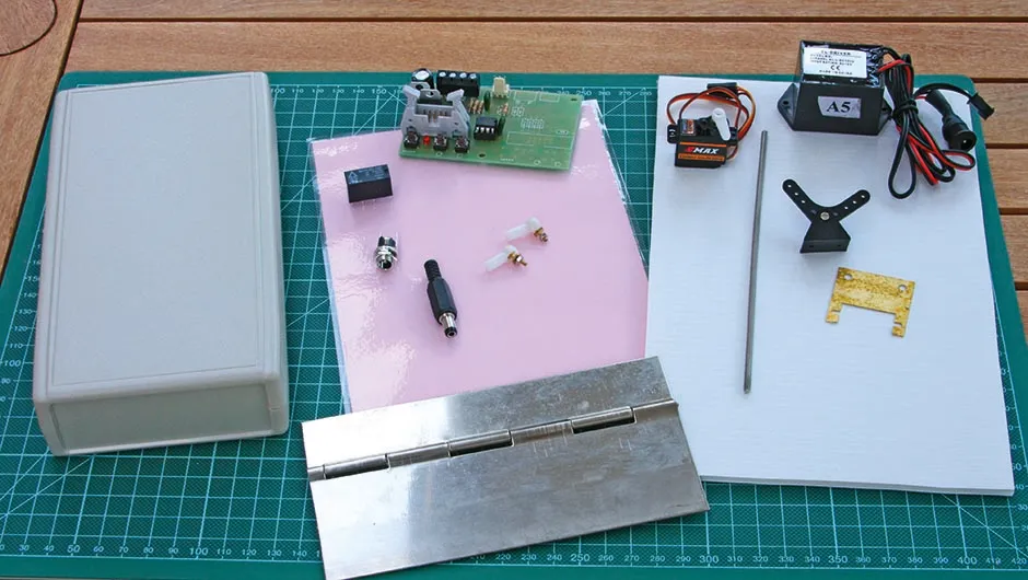
Components - Continuous hinge, project case, SPDT toggle switch, DPDT relay, DC plugs and sockets. An A5 electroluminescent panel, servo controller, servo, ball links, bellcrank and a 12V power lead.
Materials - Heavy-duty 4mm corrugated plastic sheet, 1.5mm aluminium sheet, 1mm plywood.
Tools - Cutting board, scissors, craft knife and metal straight edge, hand drill, crosshead screwdriver, 7mm spanner, soldering iron.
Sundries - Double sided adhesive tape, impact adhesive, masking tape, cable ties, wire, nuts, bolts and washers
Establishing control
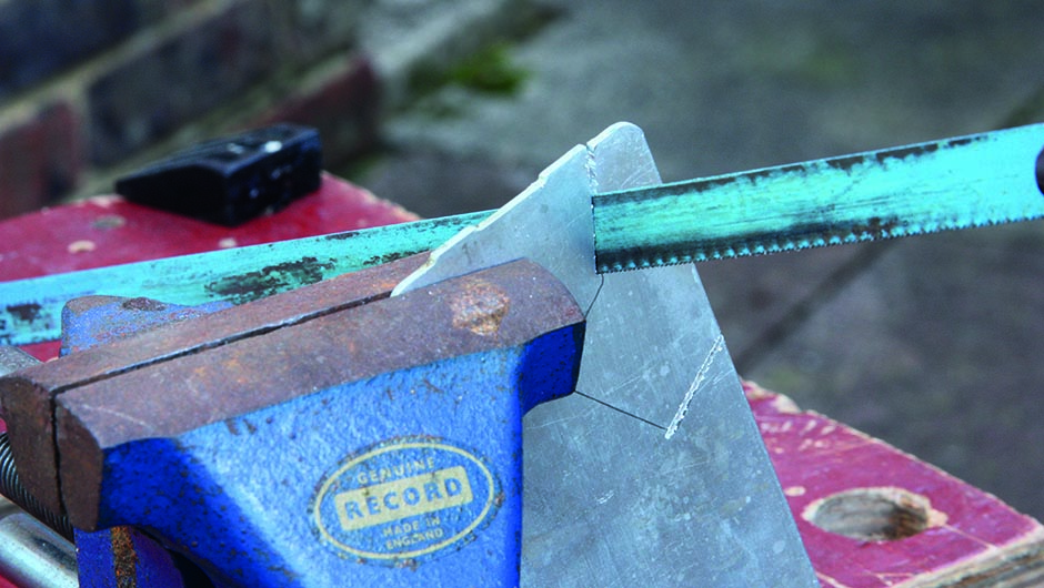
To make the custom control horn, use our template to cut a sheet of 1.5mm aluminium to shape with a hacksaw, then smooth the edges with a file.
Drill the pair of 4mm mounting holes and up to three 2mm holes for the ball link, then bend the horn into a right angle.
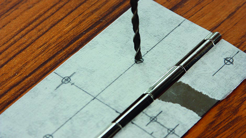
Cut a continuous hinge to size and drill two 4mm holes in one leaf for mounting to the box lid, two 4mm holes in the other leaf for mounting to the flap and two 4mm holes for the control horn.
Ensure that the vertical part of the horn is in line with the centre of the hinge.
Using the hinge as a template, leave an overhang of 15mm between the rear of the box and the hinge knuckle, and drill two 4mm mounting holes in the top of the box, ensuring that the hinge is central.
Drill two 4mm mounting holes and two 4mm holes for the custom control horn from the non-panel side of the flap.
Attach the hinge and horn leaf to the flap and the other leaf to the box lid using M4x16mm bolts, nuts and washers.
Attach the servo to the inside of the box lid with 2mm bolts, nuts and washers.
Assemble the servo arm, ball links, bellcrank and connecting rods.
Once powered, adjust the servo throw so that the flap is held closed with the switch in the ‘auto’ position and fully open when the switch is in the ‘manual’ position.
Once you have determine the best method of attaching the control box to your specific telescope and made suitable arrangements for tripping the remote connection to the unit using a USB-powered switch, you’re done.
Automated flats have never been easier.
Try even more of our DIY builds:
